Prototyping & One-Off Parts
Functional Parts for Testing, Development and Bespoke Applications
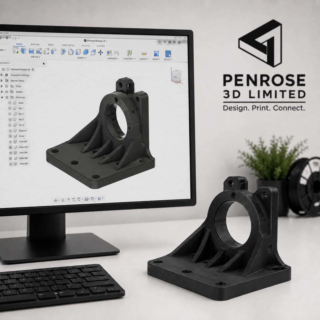
Turn your CAD design into a physical component that can be assessed, tested and improved.
Penrose 3D manufactures functional prototypes and one-off parts for businesses, engineers, designers and product development teams. From early concept models to production-representative components, we can help you evaluate form, fit and real-world performance before moving into production.
Where appropriate, prototypes can be manufactured using the same engineering-grade material being considered for the final component.
What Can a Prototype Help You Evaluate?
A physical prototype can reveal issues that may not be obvious from a CAD model or technical drawing alone.
Form and Dimensions
Assess the overall shape, size and physical proportions of the component.
Function
Test how the component performs when handled, installed or operated.
Fit and Clearance
Confirm that mating parts, mounting points and surrounding components align correctly.
Material Performance
Compare stiffness, flexibility, durability, temperature resistance and surface characteristics.
Assembly
Check fasteners, interfaces, access points and the sequence in which the component will be assembled.
User Feedback
Create a tangible component for customer demonstrations, ergonomic reviews and design discussions.
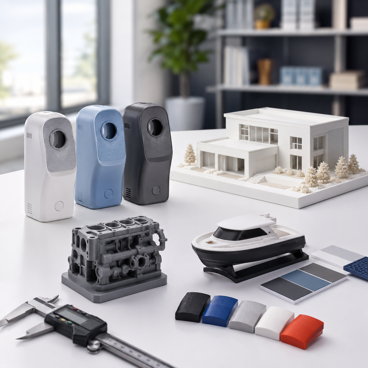
Visual Prototypes
Visual prototypes are primarily used to assess appearance, scale, shape and presentation.
They are commonly manufactured in PLA or PETG where surface quality, dimensional checking and colour are more important than demanding mechanical performance.
Typical uses:
Concept evaluation
Presentation models
Customer approval
Scale checking
Colour and branding trials
Functional Prototypes
Functional prototypes are intended to be handled, assembled or tested under representative operating conditions.
Depending on the application, they can be manufactured using engineering nylons, carbon fibre reinforced polymers, flexible TPU or high-temperature materials.
Typical uses:
Fit and assembly testing
Load evaluation
Outdoor trials
Heat exposure
Replacement-part testing
Production-material validation
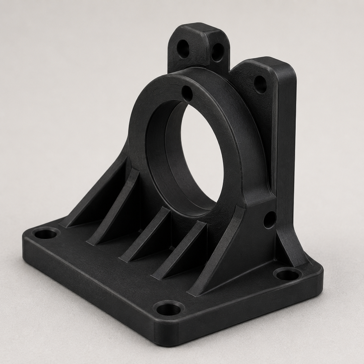
Prototype in a Material Relevant to the Final Application
A prototype manufactured in a production-relevant material can provide more meaningful information than a basic visual model.
Material selection will depend on the expected load, operating temperature, environmental exposure, flexibility, dimensional requirements and intended service conditions.
Material groups
General-Purpose Materials
PLA, PETG and PETG-CF for visual models, fit checks, housings and durable general-purpose prototypes.
Engineering Nylons
PA6, Easy PA, PA12 and PAHT-CF for tough, functional and wear-resistant components.
High-Performance Polymers
PPA-CF and PPS-CF for more demanding thermal, chemical and structural environments.
Flexible Materials
TPU in several hardness levels for grips, protective components, flexible interfaces and impact absorption.
Specialist Materials
PETG-Tungsten 75% for high-density development, weighting and specialist research applications.
Material suitability is assessed around the intended application. Published material properties do not automatically represent the performance of every finished component.
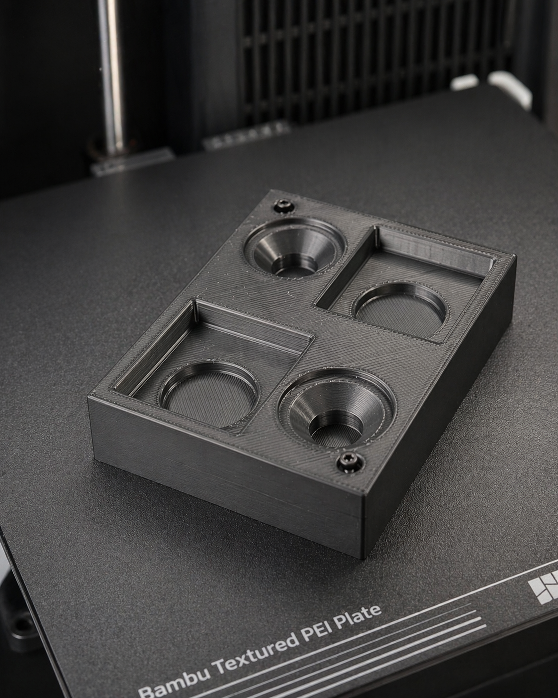
Typical Prototype Applications
Automotive and Motorsport
Brackets, ducts, covers, mounting components, driver interfaces and under-bonnet development parts.
Robotics and Automation
Sensor mounts, grippers, housings, guards, fixtures and custom machine components.
Industrial Engineering
Jigs, tooling concepts, replacement parts and components for testing new manufacturing processes.
Product Development
Physical models for evaluating dimensions, usability, assembly and customer feedback.
Specialist Applications
High-density, flexible, high-temperature or chemically resistant development components.
From CAD File to Physical Part
1
2
3
4
Files We Can Review
For the most accurate quotation, provide a production-ready file in one of the following formats:
STEP
STL
3MF
Fusion 360 compatible CAD file
Supporting drawings, photographs and sketches may also be supplied.
A STEP or native CAD file is generally preferable where dimensional changes may be required.
Maximum build volume: 300 × 320 × 325 mm
Actual usable dimensions depend on the material, geometry, orientation and support requirements. Larger components may sometimes be divided into sections for assembly.
Information to Include
Please tell us:
How the component will be used
Required quantity
Whether it will carry a load
Expected operating temperature
Indoor or outdoor use
Exposure to water, oils or chemicals
Critical dimensions and tolerances
Required fasteners or threaded inserts
Target delivery date
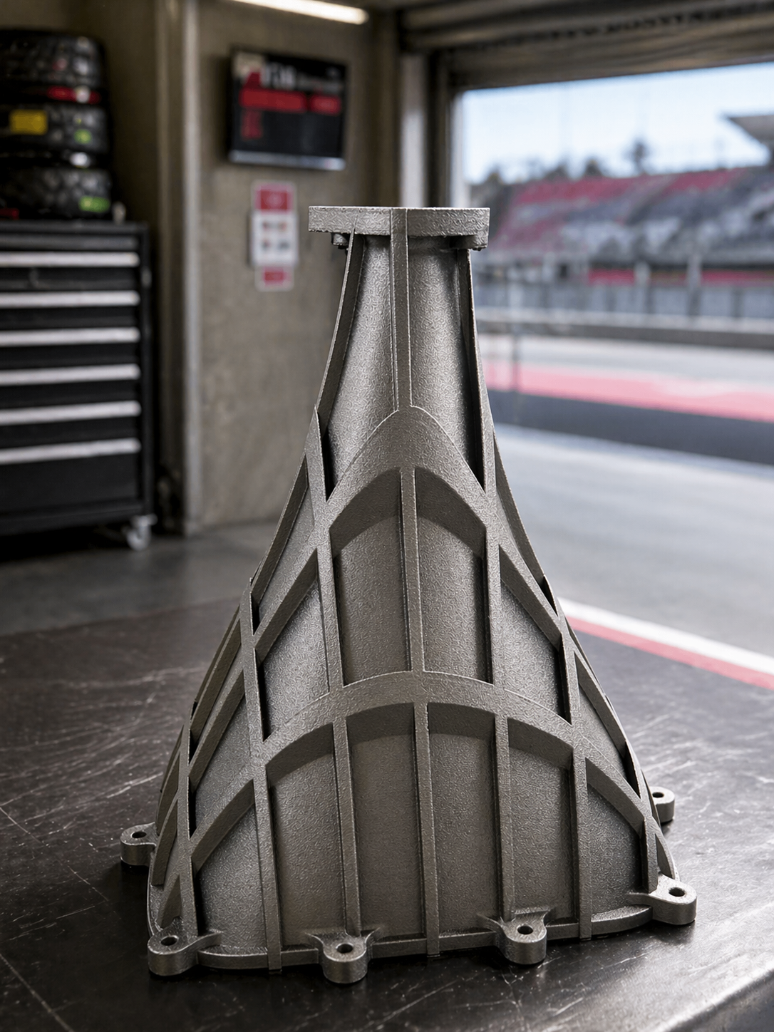
Example Project: Functional Motorsport Prototype
The Requirement
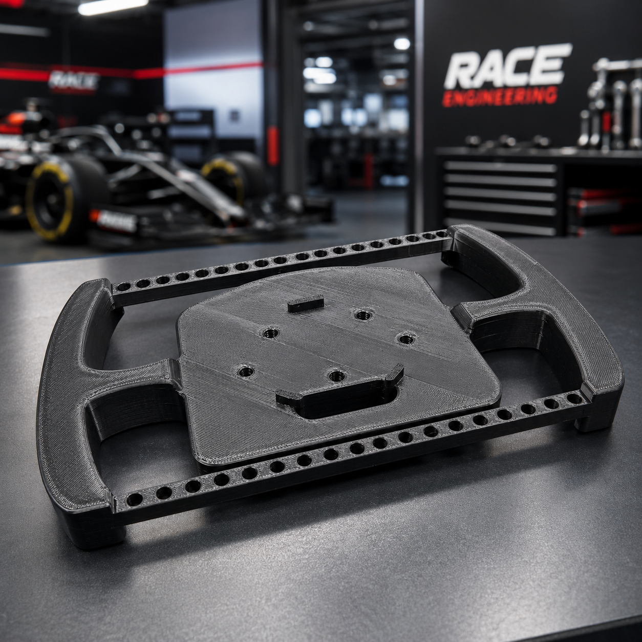
BCU Racing required a full-size steering-wheel component to evaluate fit, handling and assembly before progressing the wider design.
The Approach
The component was manufactured using engineering nylon, with an alternative support-interface material used to improve support removal and underside surface quality.
The Outcome
The completed prototype provided the team with a physical component for ergonomic review, assembly evaluation and further design refinement.
Closing line
This is a useful example of how material selection, manufacturing strategy and physical testing can work together during product development.
Frequently asked questions
-
A production-ready CAD file provides the most accurate quotation and manufacturing result. Drawings, sketches and reference images can be reviewed for straightforward projects, and CAD support may be available where modifications are required.
-
Yes, where the material, design and application are suitable. This can provide more representative testing than using a basic visual-grade material.
-
Yes. Multiple versions can be produced to compare dimensions, geometry, materials or specific design features.
-
Yes. Recommendations are based on expected load, temperature, environment, flexibility, quantity and intended use.
-
Some designs and materials can support functional evaluation, but suitability depends on geometry, build orientation, layer direction and the way the load is applied.
-
Yes. Heat-set brass inserts, typically from M3 to M6, can be installed where the component design and material are suitable.
-
The maximum build volume is 300 × 320 × 325 mm. Actual usable dimensions depend on geometry, material, orientation and support requirements.
-
Minor modifications and straightforward CAD preparation may be available. Larger or more complex design projects will be assessed and quoted separately.
Related services
Engineering-Grade 3D Printing
Explore carbon fibre reinforced, high-temperature, nylon and specialist materials.
CAD & Design Support
Prepare, review or improve a component for additive manufacturing.
Small-Batch Manufacturing
Explore carbon fibre reinforced, high-temperature, nylon and specialist materials.
Threaded Insert Installation
Add reliable fastening points for repeated assembly and disassembly.